 DASAPT
 Xinren Chen
Index two grains on the detector map, save each orientation, and calculate the misorientation across the boundary.
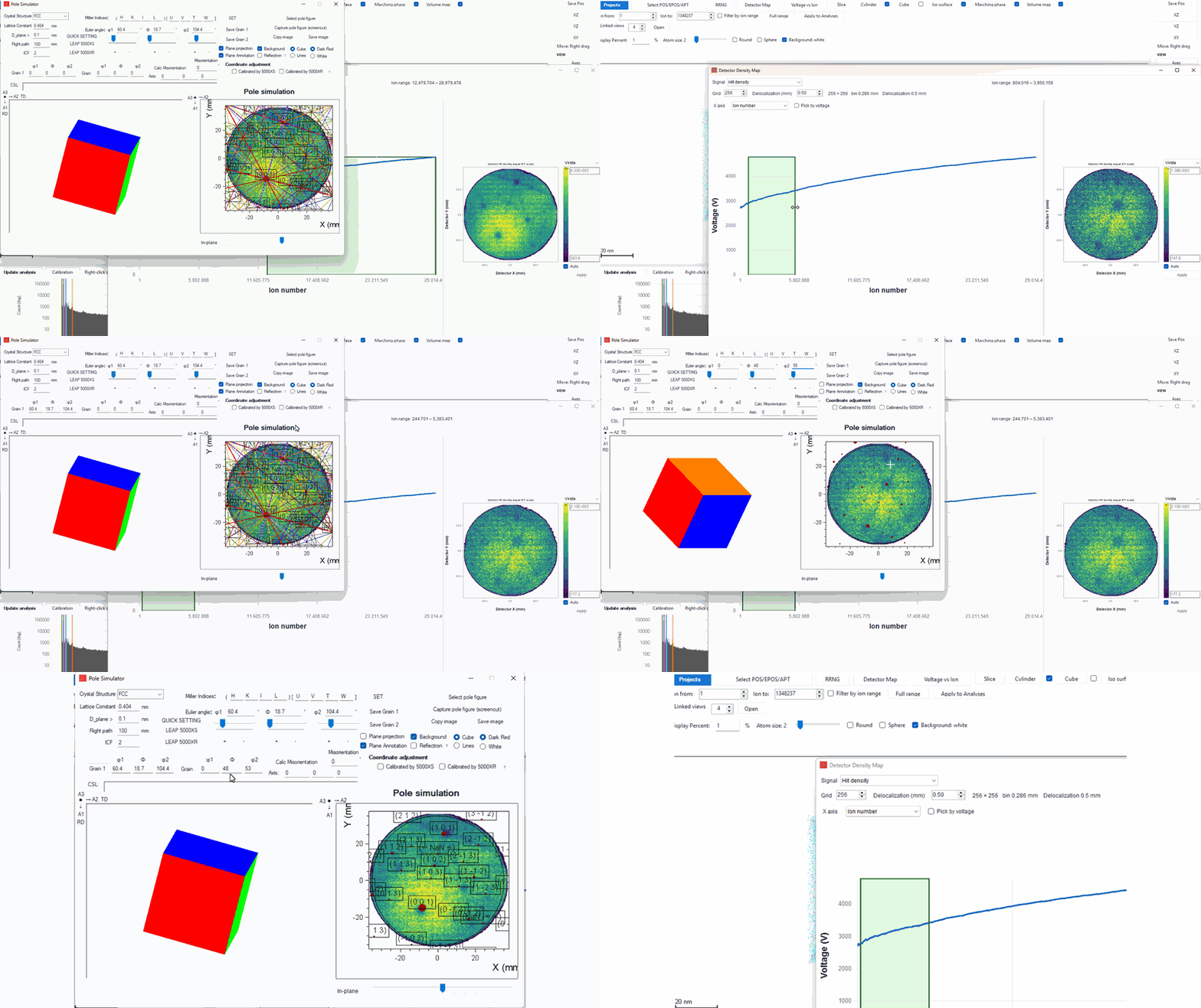
- Open Detector Map. Set Signal to Hit density, Grid to 256, and Delocalization to 0.50 mm.
- Drag the green ion-range band along the voltage curve until the poles of the first grain are clear.
- Open Indexing. In Pole Simulator, choose FCC and a lattice constant of 0.404 nm. This example uses LEAP 5000 XS, flight path 100 mm, and ICF 2.
- Drag the pole figure until the red spots sit on the dark poles, then click Save Grain 1. In the clip the first grain is φ1 60.4°, Φ 18.7°, φ2 104.4°.
- Drag the green band to a second region of the voltage curve and index that grain the same way. Click Save Grain 2. In the clip the second grain is φ1 0°, Φ 48°, φ2 53°.
- Click Calc Misorientation. DASAPT reports the minimum misorientation and the rotation axis. Here the angle is 43.7307051° about 0.0763096, −0.94339, −0.32275.
Grain 1 and Grain 2 put a saved orientation back on the pole figure.
0 comments
Sign in to comment.